By Rob Farber, contributing writer
It is well known in the high-performance computing (HPC) community that many (perhaps most) HPC workloads exhibit dynamic performance envelopes that can stress the memory, compute, network, and storage capabilities of modern supercomputers. Optimizing HPC workloads to run efficiently on existing hardware systems is challenging, but attempting to quantify the performance envelopes of HPC workloads to extrapolate performance predictions for HPC workloads on new system architectures is even more challenging, albeit essential. This predictive analysis is beneficial because it helps each data center’s supercomputer procurement team extrapolate to the new machines and system architectures that will deliver the most performance for production workloads at their datacenter. However, once a supercomputer is installed, configured, made available to users, and benchmarked, it is too late to consider fundamental architectural changes.
The goal of the Exascale Computing Project (ECP) hardware evaluation (HE) group is to modernize the metrics and predictive analysis to guide US Department of Energy (DOE) supercomputer procurements. Scott Pakin (Figure 1), the ECP HE lead at Los Alamos National Laboratory (LANL), notes, “Our main customer is the DOE facilities, who consider our work to be very valuable in determining the types of machines to be procured and configured. Our work can also be used by application developers seeking to understand the performance characteristics of their codes.”
Our main customer is the DOE facilities, who consider our work to be very valuable in determining the types of machines to be procured and configured. Our work can also be used by application developers seeking to understand the performance characteristics of their codes. — Scott Pakin, ECP HE lead at LANL

Figure 1: Scott Pakin, ECP HE lead at LANL.
Addressing the Complexity of Modern System Procurements
Many modern supercomputers now contain both CPUs and GPUs, which have their own separate memory systems and run according to different computational models. CPUs, for example, are general-purpose multiple instruction, multiple data (MIMD) processing elements in which each processor core can run a separate task or instruction stream. On the other hand, GPUs use a single instruction, multiple thread (SIMT) execution model that provides a form of coarse-grained task parallelism. Some applications require fine-grained MIMD processing, which means they can only run efficiently on CPUs, whereas others can run efficiently on both CPUs and GPUs, and procurement teams must account for this. However, future systems could contain devices that run according to a non-von Neumann execution model. Potential devices include coarse-grained reconfigurable arrays and future artificial intelligence accelerators.
The ECP must address these and other complexities. For this reason, the HE portfolio focuses on integration with facilities to answer the following questions.
- How well can ECP applications expect to perform on future hardware?
- Where should facilities focus their efforts in terms of helping applications exploit upcoming hardware?
- What hardware alternatives (e.g., node architectures, memory layout, network topology) would most benefit DOE applications?
Experience has shown that HE often serves as a bridge between application development (AD) and facilities in which AD is focused more on “here and now” performance. HE takes a more future-looking approach that can provide advance information to facilities. Nick Wright (Figure 2), the Advanced Technology group lead and National Energy Research Scientific Computing Center (NERSC) chief architect, notes, “Along with helping us define the characteristics of our production workload in a manner that is useful for future hardware procurements, the ECP HE effort has also provided useful information to our application teams to help optimize our workloads.”
Along with helping us define the characteristics of our production workload in a manner that is useful for future hardware procurements, the ECP HE effort has also provided useful information to our application teams to help optimize our workloads. – Nick Wright, Advanced Technology group lead and NERSC chief architect

Figure 2: Nick Wright, Advanced Technology group lead and NERSC chief architect. (Source: Nick Wright.)
Evaluating CPU/GPU Data Movement
Modern GPUs support two mechanisms for moving data between CPU memory and GPU memory. Programmer managed memory requires that the programmer manually allocate and explicitly specify each data movement in terms of contiguous blocks of data on each device. The relatively recent addition of GPU Unified memory with hardware support means that pages of data can be moved between devices automatically on demand, without explicit programmer intervention. In this way, unified memory can support the movement of complex and sparse data structures. (For more information see https://developer.nvidia.com/blog/unified-memory-cuda-beginners/).
Programmer managed memory is more difficult to use but can lead to superior performance if employed carefully because the programmer has the ability to explicitly specify fast, bulk data transfers and even choreograph the asynchronous overlapping of computation and data movement. In contrast, unified memory relies on “smarts” in the hardware (implemented via the hardware memory management unit or MMU) to determine when pages of data are needed by either the CPU or GPU. Sometimes, the hardware cannot minimize time consuming data movement as well as a knowledgeable programmer, but this is not always the case. Overall, the ease of use and benefits of unified memory are hard to deny – especially as it is well suited for complicated data structures and access patterns for which the programmer also cannot determine the best way to transfer data between devices.
Programmer managed and unified memory are not mutually exclusive. In fact, it is reasonable for an application to use programmer managed memory to transfer regular data structures (like a matrix) and unified memory to transfer irregular data structures (like an in-memory database or a graph). Scott Pakin notes, the HE team investigated this use case and found that it can lead to excessive data movement, as shown in Figure 3. Part of the reason is that on current GPUs, memory explicitly allocated on the GPU takes precedence over unified memory that can migrate between CPU and GPU—even if the latter memory is more critical to an application’s performance. As a result, unified memory can be repeatedly evicted from the GPU to CPU to make room then brought back as soon as it is again required.
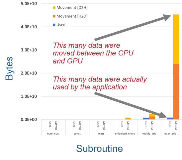
Figure 3: Identification of excess data movement between the CPU and GPU memory systems. (Source: the ECP.)
Investigations like this provide three main benefits:
- inform facilities, AD, and software technology of excess data movement causes in CPU/GPU interactions;
- provide new and enhanced tools that relate excess data movement to application data structures and access patterns; and
- identify potential ways to reduce excess data movement.
Instruction Mix Analysis
CPUs execute a variety of instruction types. Pakin notes that integer instructions typically execute faster than floating-point and branch instructions, which execute faster than memory instructions. Consequently, the mix of instructions an application executes correlates with application performance. This mix is not normally fixed but can depend on how the application is run. As an experiment, the HE team kept an application—in this case, the SW4Lite proxy application—and its inputs fixed while they varied the level of hardware thread parallelism the application was allowed to exploit and observed how the instruction mix varied by kernel routine.
Figure 4 presents the resulting measurements. Of the sixteen kernels, nine are dominated by various types of floating-point operations (FPOPS, DPOPS, SPOPS, and FMAINS), and the ratio changes little with increased parallelism. This indicates that those kernels are likely to observe good performance even with increased parallelism. However, five of the sixteen kernels are dominated by memory operations (the blue LSTINS bars), and a few of those see an increase in the fraction of memory operations with increased parallelism. The implication is that the performance of those kernels will become dominated by the memory subsystem as parallelism increases and therefore run slower than an application developer might hope.
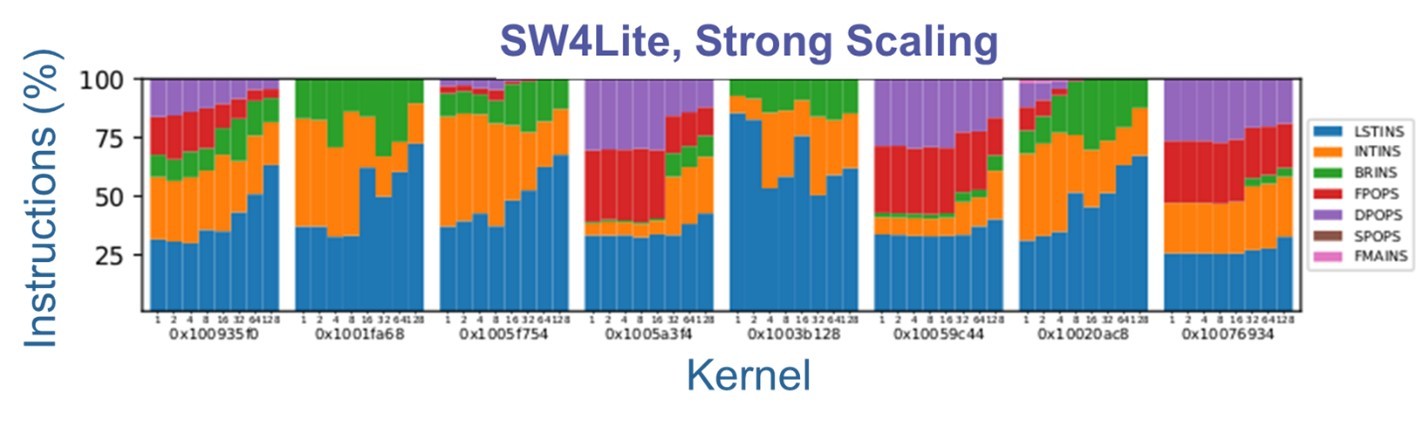
Figure 4: Categorization of instruction mix. In the color key on the right, LSTINS are the load-store instructions, INTINS are the integer instructions, BRINS are the branch instructions, FPOPS are the floating-point operation instructions, DPOPS are the double-precision operations, SPOPS are the single-precision operations, and FMAINS are the Fused Multiply-Add instructions.
The team believes that this analysis capability will help guide the Facilities in future procurement, as well as guide AD in development and tuning activities. It can guide Facilities by indicating where performance gains from increased core counts may begin to peter out. At such a point, Facilities may favor CPUs with fewer hardware threads per node but more performance per thread. Similarly, AD can utilize this capability to help identify the sources of reduced efficiency as thread counts increase.
Understanding the Effectiveness of Network Congestion Control
On HPC systems, competition for network bandwidth can arise from multiple sources both internal to the application as well as from competing jobs running on other parts of the system. Some HPC systems are also designed so that I/O traffic is also routed across the supercomputer fabric, rather than though a separate storage fabric, which means that file and storage I/O can also cause network congestion that can slow application performance.
The HE team recently reported progress in understanding the effectiveness of network congestion management and quality of service (QoS) (i.e., priority levels) in the presence of I/O and other many-to-one (N:1) communication patterns.
The findings shown in Figure 5, based on large-scale network simulation, indicate that QoS and congestion management can effectively mitigate interference of N:1 traffic with other applications. The orange line represents an N:1 workload that saturates an I/O server in a multi-job environment. The blue line represents an application, in this case a “Halo3D” microbenchmark that alternates computing and communicating with its nearest neighbors on a 3‑D grid. The spikes in the graph are caused by these periodic bursts of communication. Without congestion management, the N:1 workload would consume all the network bandwidth, flattening the spikes and delaying the application’s execution until the N:1 workload completes. With congestion management, the case represented in the figure, the bursts of communication continue largely on schedule while the N:1 workload still receives substantial bandwidth when the application does not require it and only slightly degraded bandwidth when both traffic patterns communicate simultaneously. In short, congestion management helps reduce congestion on the network fabric and more fairly allocate network bandwidth across jobs, which could lead to less variation in run time for applications as well as higher performance.
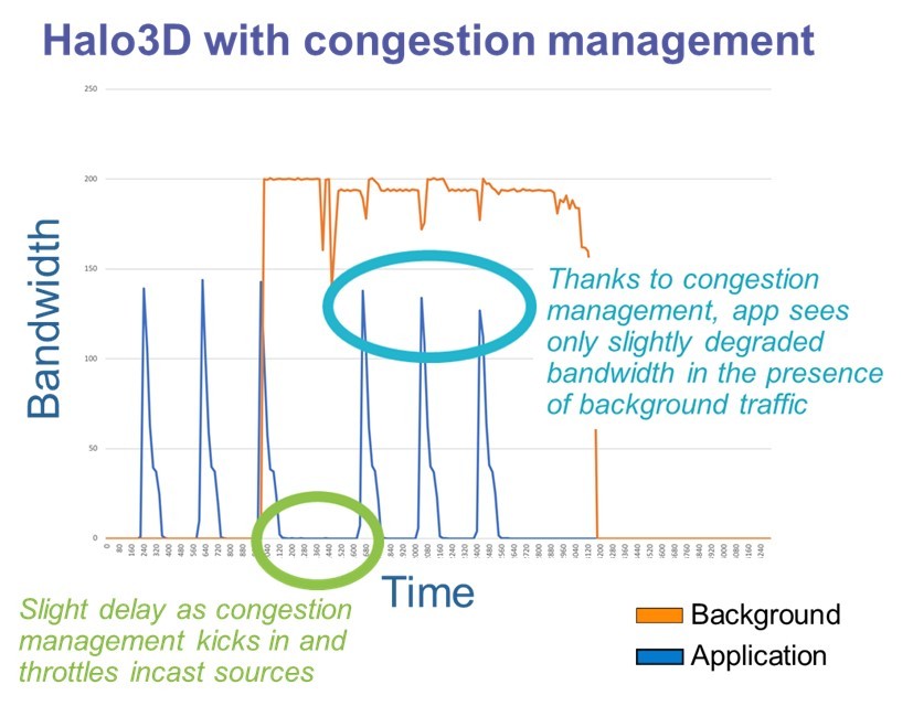
Figure 5: Example results for a congestion management benchmark. (Source: the ECP.)
The team thinks this will help in the selection and configuration of supercomputer networks and storage infrastructure, as well as help avoid the worst-case network congestion scenarios.
Other Tools: Roofline Model
The HE team also uses the well-regarded roofline model, which can expose several computational limitations in both CPUs and GPUs. The roofline model plots computation rate (floating-point operations per second) against computational intensity (floating point operations per byte transferred from the memory subsystem) and represents the maximal performance achievable for a given computational intensity. The name derives from the shape of the curve, which looks like a roofline: a linear increase in performance until some threshold computational intensity is reached followed by a horizontal line of constant performance once the processor has reached its peak computation rate. An application is plotted as a point on that graph based on its observed computation rate and computational intensity. The distance between that point and the roofline quantifies the amount of inefficiency in the application and how much additional performance can be gained. The graph also indicates if a performance benefit can be observed if it is possible to increase the application’s computational intensity.
In some recent work, the HE team used the roofline model to develop roofline scaling trajectories for two sparse numerical kernels, SpTRSV (sparse triangular solve) and SpTRSM (sparse triangular solve with multiple right-hand sides), running on GPUs. This means they analyzed how changes to cache and memory access locality, warp efficiency, and streaming-multiprocessor and GPU occupancy relate to where the corresponding point appears on the roofline graph. The challenge in performing this analysis is the kernels’ data dependencies. To address this challenge, the team constructed directed acyclic graphs of these dependencies and used these to produce trend lines of application performance and arithmetic intensity for different amounts of concurrency.
Summary
The ECP HE team was formed to provide the ECP and DOE facilities with hardware knowledge and analysis capabilities. New hardware architectures, tiered memory systems, and other advances in computer architectures have required modernizing project metrics and the predictive analysis used in system procurements.
Once a supercomputer is installed and prepared for production runs, it is too late to consider fundamental architectural changes. The ECP predictive analysis effort is beneficial because it guides DOE supercomputer procurements toward the systems that deliver the most performance to the extreme-scale applications of interest to DOE.
Rob Farber is a global technology consultant and author with an extensive background in HPC and in developing machine learning technology that he applies at national laboratories and commercial organizations. Rob can be reached at [email protected]